
I have had five lift kits in my 76 and was not satisfied with any of them, especially in the front.
So about three years ago I was thinking of doing some kind of link suspension in the front, but I could not think of a way to fit the links in the chassis of the bronco. About 1 1/2 years later I saw some shorty headers for the mustang 5.0 and that was it, I had found a way to fit the four links I needed to pull it off.
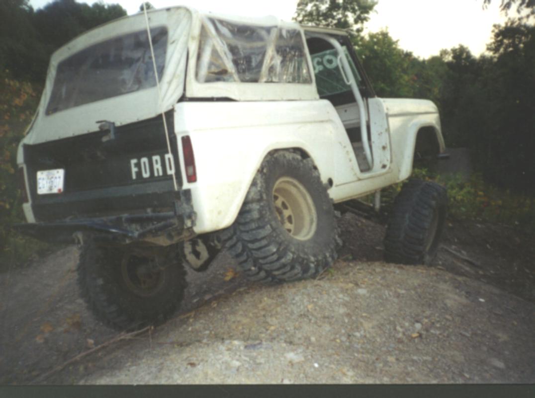
The main reason I wanted a more flexible front end is because the front of the bronco acts as a giant sway bar. It limits the front from flexing by design. This may be why the bronco does so well at the tuff truck competitions. It handles well for a four-wheel drive truck, but I wanted stability and flex for off road.
With the front not flexing as well as the back, it makes the truck and chassis follow the terrain that the front axle is on. In other words, if you are going up hill and the right front tire climbs a rock, it will force the body to lean to the left and make the rear suspension do most of the flexing. Whereas if the front had a better degree of flex it would ideally do half or a percentage of the flexing, keeping the body level.
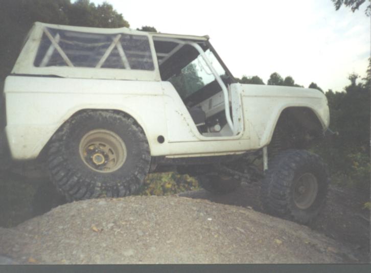
Having a flexible suspension may not increase traction but it certainly does increase stability and install a higher degree of confidence.
Well I started buying up the material I needed:
|
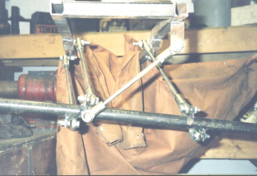
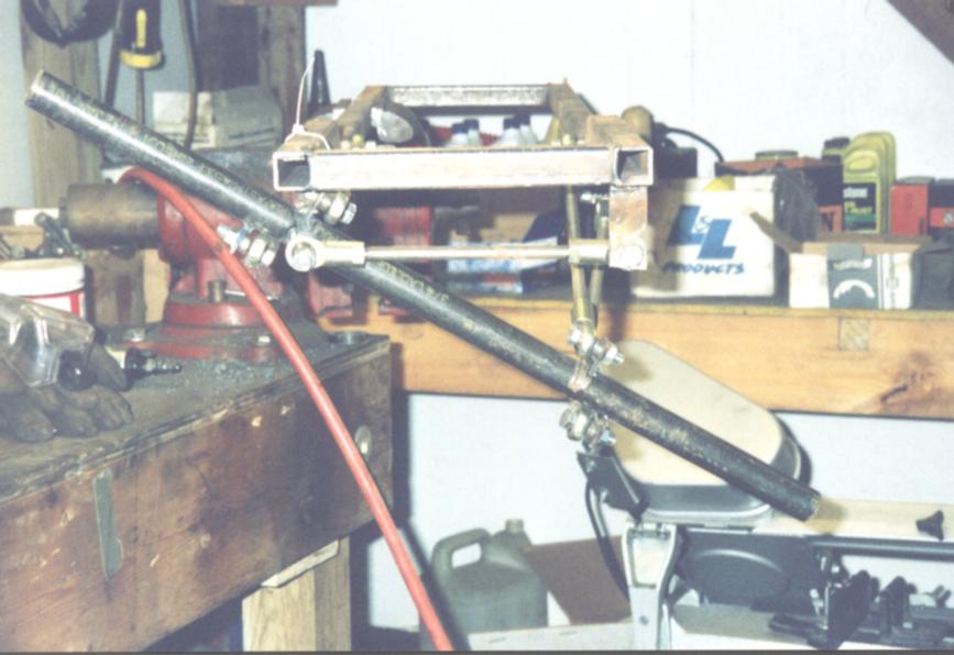
The first thing that I did was to build a 1/3 scale model.
 |
 |
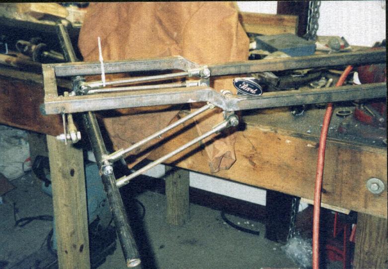 |
If you are planning to do something this radical I suggest doing the same. I spent a considerable amount of time and money on this model and it was worth every bit of it. I learned a lot from this model. Things like link placement, amount of deflection, degree of deflection, what changed when I would move the attachment points, etc. This model is a lot easier to work with than the full size arms and the axle.
I measured every dimension that I would be working with- axle width, link separation, frame width, frame length, rod length, etc, and divided by 3.
When I was satisfied with all the movements and placements of the links I started to work on the truck.
I removed the front axle assembly and started removing the "C"
bushing lobes from the axle.
This proved to be more difficult than I thought. Lets just say that I don't think we have to worry about them falling off!
To remove them I used a cutting disc to cut along the welds that run along the axle length. Then ground the area smooth.
I wanted to keep the factory radius arm mount
on the frame for a few reasons. One for the stealth look and because I
like the mount. It provides all of the axis of movement needed, its simple
and is also quiet.
I also wanted to keep the same angle of flare from the frame to the axle. What I'm calling flare is looking down at the frame and where the rear of the arms attach to the frame is narrower than where the arms attach to the axle. This angle is 10 degrees to the frame.
So I measured the axle and marked the location of the lower mounts.

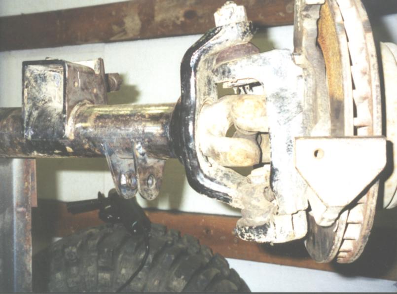
For the top mount I cut and widened the panhard rod mount that is on the top of the passenger side axle by 10 degrees. This allows the top rod to mirror the 10 degree flair of the lower bar.
For the frame mount of the upper link I drilled a 10 degree hole through the frame and inserted a 1-inch OD piece of tubing and welded it to the frame. This would form one side of the top mount. For the other side of each mount I cut a piece of 4x3 squire tubing to form a strongback. The upper rod end is now in a double shear mount.
All the links are the same length and are all at a 10 degree angle to the frame. They are all the same distance apart at the ends. This forms a neutral suspension, meaning that there is no binding in its entire range of motion. Some people will tell you that this is not good. But to build in some kind of binding is exactly what I did not want to do. That is what swaybars are for. Plus it would be hard to do using rod ends without over stressing any one joint.
The final product is very stable. So stable in fact that I took
it to the drag strip and turned an 8.7 at 73mph in the 1/8th
mile. 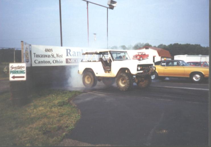
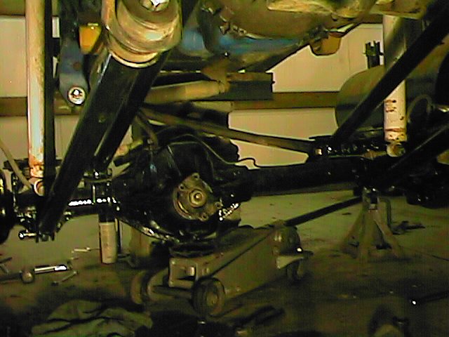
For the upper mount on the axle I had to incorporate it into
the center section.
This material is called malleable iron and does not weld very
well, so proper welding techniques are required. Pre-heating and post-heating
is also a good idea.
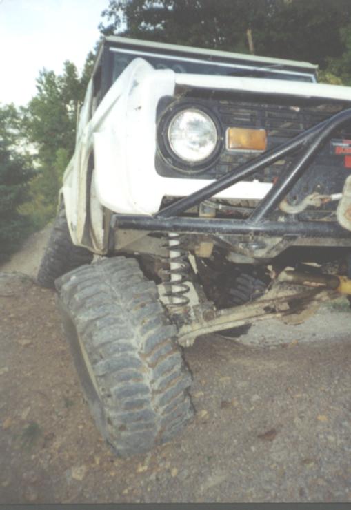
Now that the factory radius arms are gone I had to build the lower retainment for the spring.
 |
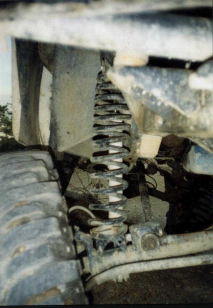 |
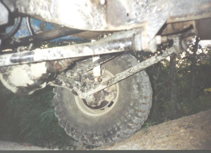
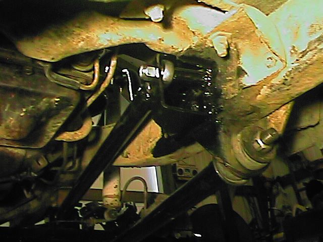
For this I used 4x4 square tubing. I also incorporated the lower
shock mount into this mount. Also in this shot you can see how I relocated
the bump stops. With the axle now being able to deflect better than 25
degrees, the bump stops would not align with the frame. If they are on
the frame they will always make contact with the axle at any angle. The
only thing I would change would be the rod ends. They have not been on
long enough to become noisy (only about 11 months), but I have no need
for the multi-able axis they provide. Some of the street rod shops have
some nice and beefy rod ends with rubber bushings that I think would prove
to be more durable.

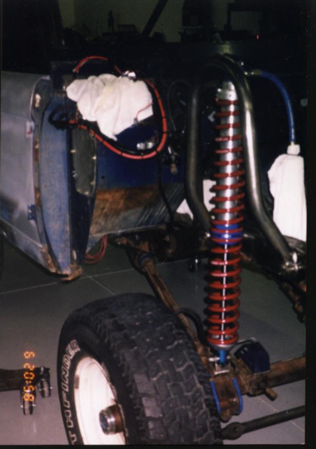
To finish this project I'm looking into a set of coilovers.
This project proved to be very rewarding. I learned a lot. The
performance is unmatched by any after market suspension system. And like
any good project it consumed every idle thought.
Now for the back. If I could fit….,
Thank you for reading.
jim
Page by Jim Howell - last modified 01/27/00
©2002 copyright BroncOhio Early Bronco Club.